Table of Contents
Submission Information
Date: Wednesday, January 14, 2009.
Submitted By: Group 8
- Liliane Barbour
- Jonathan Mash
- Michael Studli
Faculty Supervisor:
- Dr. Hashtrudi-Zaad
- Department of Electrical and Computer Engineering
Download
EXECUTIVE SUMMARY
This document summarizes the progress of the Smart TV project. The goal of this project is to research, design, and build a working model of a television stand that adjusts the TV volume and rotates to achieve an optimal viewing position by sensing the position of its viewers. The project is made up of three systems, a sensing system to determine to position of viewers, a controller to compute the ideal position and volume of the TV, and a drive system to accurately rotate the TV to the previously calculated position.
The team has spent the past semester testing and designing the individual hardware components of each system. When testing the existing sensor system, it was found that the PIR amplifiers were becoming saturated, resulting in a clipped output. The existing PING sensor used the I2C interface, so a new digital PING sensor was selected for the project. Two motor controller systems were designed, one using an off-the-shelf H-Bridge IC and the other a custom H-Bridge. Time and budget permitting the custom design will be implemented. After much discussion the Arduino microcontroller was selected for this project because of the adequate number of inputs and outputs, memory space, ease of programming, and fast processing speed. The team has developed a three step software development process that will allow testing of the software interface with all systems before the intelligence algorithm is applied.
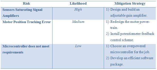
The team has outlined three different possible problems that may occur, and the measures being taken to prevent them from occurring. The issue of amplifier saturation will be dealt with by using a variable amplifier. Motor position error will be prevented by investigating the use of a potentiometer to give feedback on the position of the TV. Insufficient microcontroller issues, such as speed and memory will be prevented through efficient coding practices.
Designs were drawn up and parts were ordered. Most significant parts arrived on January 8, 2009. Team members have supplied any outstanding parts until they can be acquired. The team has yet to order parts for the volume control system, an Arduino microcontroller, and PCB boards. They have budgeted for these purchases and expect to remain on budget. It is estimated that the total cost of the project will be less than $400.
In terms of scheduling, the research phase is complete. The design phase is behind schedule in certain areas, but the team has already started parts of the prototyping phase in an attempt to remain on schedule. Integration of the full system is the next major milestone. The team expects no problems in completing the project on schedule.
INTRODUCTION
PURPOSE
This blueprint document is intended to summarize the progress of the ELEC 490 project being undertaken by group eight. The intended audience is the course instructors, Dr. Hashtrudi-Zaad, as well as any interested parties.
ORGANIZATION OF REPORT
This report gives an update on the status of the Smart TV Project. A work breakdown structure summarizes the completion of individual tasks. A detailed summary of the progress-to-date includes details about the testing and design phases. Also included is an updated budget. Lastly, a list of potential problems and the steps being taken to prevent their occurrence is presented.
PROJECT OVERVIEW
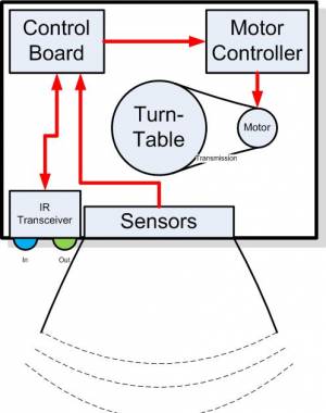
The goal of this project is to design a Smart TV which can rotate to optimize the viewing position of all viewers. The system should be non-intrusive, meaning that the television’s electronics will not be altered. The project is composed of a three-part framework: a sensing system to determine the position of viewers, a controller to compute the ideal position of the TV, and a drive system to accurately rotate the TV to a previously calculated position. See Figure 1 for a graphical representation.
Figure 1: System level overview
WORK BREAKDOWN STRUCTURE
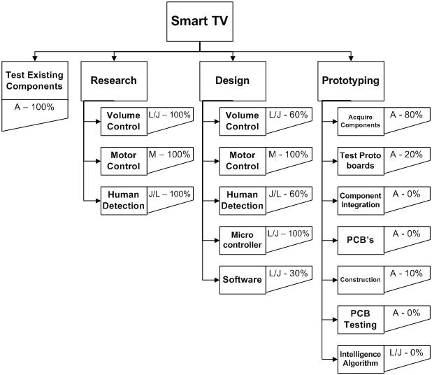
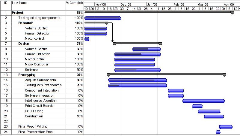
Figure 2: Work Breakdown Structure
NOTE: L=Liliane, J=Jonathan, M=Michael, A=All or unassigned. Percentages indicated are percent of task complete.
PROGRESS TO DATE
WORK COMPLETED
TESTING EXISTING COMPONENTS
The team acquired the existing television base that was used two years ago by another ELEC 490 team. There were several sensor systems that had to be tested, including five PIR sensors, a PING sensor, the volume control system, and the IR receiver system. The methods used to test each sensor are described below.
BASE: The base included a Plexiglas cover in front of all the sensors. None of the sensors appeared to function properly while the Plexiglas cover was in place. It was determined that the cover did not allow infrared light to penetrate through to the sensors. Removing the cover solved the problem. The team will look into infrared permeable plastic covers.
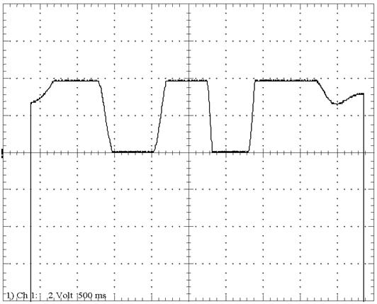
PIR SENSORS: The PIR sensors produced the output expected from the specification sheet, but there was significant overlap in the field of view of the sensors. The output from the sensors was tested at different distances and in both directions across the field of view. It was found that the sensors saturated the amplifier used to boost the output. An oscilloscope screenshot can be seen in Appendix A. This means that a new amplifying circuit will need to be developed. The saturation will need to be taken into consideration when designing the intelligence algorithm.
PING SENSOR: The existing PING sensor used the I2C interface which means that it was not possible to view its output directly on an oscilloscope. To compensate for this, the sensor was connected to a BASIC Stamp and the output was displayed on a computer terminal. The PING sensor worked as expected. The team then tested a second PING sensor manufactured by Parallax (1). The new sensor was provided by a team member. The new sensor uses a digital interface, and was found to have a much greater range than the I2C PING sensor. For these reasons, the Parallax sensor was chosen for this project.
VOLUME CONTROL: The volume control system consists of a 555 timer which sends a 40 kHz pulse to a transistor which, in turn, flashes an infrared LED on and off. The IR receiver for the remote control receives a signal and sends it to a microcontroller as a digital input. In order to test the volume control system, the team attempted to send a signal from the 555 through the volume control system, and receive it back through the IR receiving circuit. The output from the IR receiver was displayed on an oscilloscope. This did not work, so a new testing method had to be developed.
The volume control system was tested as described above, but an oscilloscope was used to view the output at the transistor. It was found that the existing timer output a pulse at a frequency of 27 kHz – this is not sufficient for controlling a television. The team decided that the volume control (the IR transmitter) system will have to be redesigned. The IR receiver was tested by connecting it to an Arduino microcontroller. A simple program to decode an IR remote control signal was acquired from the Arduino web site. A remote was used to send a signal to the IR receiver, and the output was displayed on a computer terminal. The IR receiver works as expected.
MOTOR CONTROLLER: The existing motor controller circuit was not tested due to the team’s lack of understanding of the circuit, the poor construction of the circuit, and the complexity of the wiring.
DESIGN
MICROCONTROLLER SELECTION
Due to the nature of the sensors that are being used in this design, a powerful processor with fast analog to digital conversion is required. Also, analysis of five analog channels (for five PIR sensors) is required to determine the position and movement of humans in the TV’s field of view. These requirements indicate that the microprocessor must have enough memory and fast enough clock speed to read, store, and analyze potentially thousands of samples per second.
Given these requirements, the team researched and selected several possible candidates for the main control board. Among other selections, the team evaluated the PIC Explorer 16 EVB, the PIC Wireless Discovery Kit (borrowed from Technical Services), and two open source microcontroller packages. Of these selections, the team decided to use the Arduino microcontroller.
The Arduino is an easy to use microcontroller package that is based on the ATmega168 microprocessor (1). The term Arduino usually refers to the entire package which comprises of the PCB design, software API, programming IDE, and the bootloader. The Arduino system is open-source and publically available. The Arduino comes with an ATmega168 chip that is preloaded with the Arduino bootloader. The bootloader is used to easily program the chip without the use of and In-Circuit Serial Programmer (ICSP). This allows for quick and easy development at the loss of a small amount of program memory. The ATmega168 chip has 16kB of flash (program) memory, 1kB of SRAM (variable) memory, and 512 B of EEPROM (long term storage) (1). Although this is a relatively small amount of memory, the team is confident that it will suffice for the purposes of this project. The processor currently runs at 16 MHz but can be run up to a maximum of 20 MHz (2). This processor speed should be more than enough for the team’s purposes. The Arduino also has six 10-bit analog to digital converters and over ten digital I/O pins (1). This should be suitable for the team’s application.
SOFTWARE DEVELOPMENT
The software will be built in three stages. The first stage, which began as soon as the team selected the microcontroller, was to write code that can communicate with each individual device. Once this is complete, the team will start combining the software for the individual systems into one package. Inputs will be read from the sensory system, but no decisions will be made based on the input. Hard-coded data will be sent to the volume controller and motor controller. In the third stage, further development will implement an intelligence algorithm. It will take data from the sensors, and then make decisions that affect the output sent to the volume control system and motor controller. Since the intelligence algorithm is dependent on the integration of the hardware systems, full development and testing of the algorithm will occur after hardware integration begins, as can be seen in the Gantt chart in Appendix C.
MOTOR CONTROLLER
It was decided in the meeting with Dr. Hashtrudi-Zaad on November 20, 2008 (4), that two motor drivers will be developed. The first system will comprise of an off-the-shelf H-bridge integrated circuit that has all the basic capabilities necessary to run the stepper motor found in the turntable design. Time and budget permitting, a second system will be built. It will consist of a custom H-bridge controller with over-current protection that can be built to the exact specifications of the stepper motor. The two systems will require the same inputs and have the exact same outputs; this will reduce the amount of I/O required from the microcontroller and allow the two systems to be easily interchangeable.
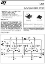
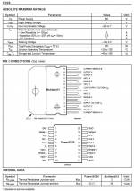
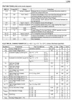
The first system will use the L298HN Integrated circuit manufactured by STMicroelectronics (refer to Appendix D for additional information). Its specifications suggest that it can provide a DC current of 4 amperes, over-temperature protection and an operating supply voltage of up to 46 Volts. It comes in a 15-lead multi-watt package accepting TTL logic levels for control and delivers high current through its full-bridge driver. It also comes highly recommended for inductive loads such as solenoids and DC stepper motors. Furthermore, it has an enable pin which can be controlled from the microcontroller to provide the ability to be bypassed and/or turned off. This will be beneficial when integrating our second system.
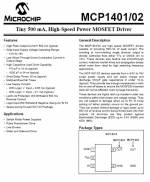
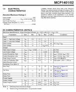
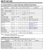
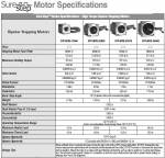
The second system will be a custom designed H-Bridge driver made specifically for the bi-polar stepper motor. It will be designed to provide 2.8 amperes per phase, with a resistance of 0.75 Ohms and an inductance of 2.36 mH (please see Appendix F for more information). The design is also going to integrate an automatic current limiter and temperature overload capability. The H-bridge will be powered by MOSFETs and driven by MOSFET drivers obtained from Microchip Technologies analog components (model number MCP1401 – see Appendix E for more information on this component). The off-the-shelf system is simplistic and industry proven. A custom system will allow the team to explore working with analog motor control and sensory circuits. It will also include over-current protection as an added safety feature. The use of the two systems should lead to a successful implementation of the motor controller driving circuit.
CONTROL BOARD AND MOTOR CONTROL BOARD INTERFACING
In a team meeting on January 7, 2009 (4), the team members decided on a PWM control system to serve as the basis for interfacing between the control board and the motor control board. The length of a single pulse will indicate the desired position of the TV in degrees. This design is very similar to a servo controller that uses a base timing of 1.5 seconds and a range of 1 to 2 seconds. One second would refer to the minimum possible rotation and 2 seconds refers to the maximum possible rotation. Exact timing specifications will be finalized during programming of both the central controller and motor controller boards.
CHANGES SINCE THE PROPOSAL
SCHEDULING
All parts were ordered before the winter break. They arrived much later than expected on January 8, 2009. The team will now begin to prototype their designs.
The selection of the microcontroller took much longer than expected. Now that the microcontroller has been selected, it is possible to begin planning the intelligence algorithm. See Figure 2 for a detailed work breakdown structure and completion information. All these changes are reflected in a revised Gantt chart which can be seen in Appendix C.
The research phase is complete. The design phase is behind schedule in certain areas, but the team has already started parts of the prototyping phase in an attempt to remain on schedule. Integration of the full system is the next major milestone. The team expects no problems in completing the project on schedule.
DIVISION OF LABOUR
Michael has spent the past semester investigating a new motor and designed a new motor drive-train. Jonathan and Liliane worked on testing the existing sensors, researching new sensors, and investigating a new volume control system. Jonathan focused on new designs for the sensor circuits, while Liliane researched and selected the microcontroller.
BUDGET
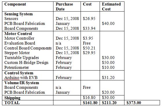
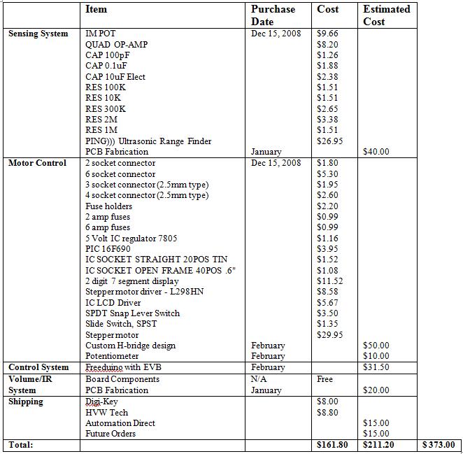
A summary of the current budget can be seen below. All major components have been ordered. Some components, such as the motor controller evaluation board, have been provided by team members. Another team member has provided an Arduino microcontroller and evaluation board for prototyping, but the team will purchase a new unit once it has been determined that it will meet the needs of the project. All PCB boards have yet to be ordered, but will be ordered in early February. A detailed budget with a list of all components can be seen in Appendix B.
Table 1: Summary of Current Budget
PROBLEMS AND RISK MITIGATION
CONCLUSIONS
In this blueprint document, the team summarized their progress to date. They have completed the testing and research phases, and are well into the design phase. They expect to begin prototyping immediately. Selection of the microcontroller put the software component of the project slightly behind schedule but the team expects the project to be completed on-time in early March. They have considered two possible designs for the motor controller, and will investigate creating a custom motor controller, time permitting. The team has considered several possible problems that may occur such as motor position error, sensor amplifier saturation, and microcontroller capabilities. They have outlined possible solutions and ways to minimize the occurrence of these problems. By early March, the team expects to have a working model of the Smart TV. The team expects to remain within budget with an estimated budget of $373.00.
REFERENCES
- Parallax. PING ))) Ultrasonic Sensor. Parallax. [Online] [Cited: Jan 14, 2009.] http://www.parallax.com/Store/Sensors/ObjectDetection/tabid/176/CategoryID/51/List/0/Level/a/ProductID/92/Default.aspx?SortField=ProductName%2cProductName.
- Contributors, Arduino.cc. Arduino Diecimila. Arduino. [Online] [Cited: Jan 14, 2009.] http://arduino.cc/en/Main/ArduinoBoardDiecimila.
- Atmel. ATmega168 Datasheet. Atmel. [Online] [Cited: Jan 14, 2009.] http://www.atmel.com/dyn/resources/prod_documents/2545S.pdf.
- Studli, Michael. Meeting Minutes - November 20, 2008. ELEC490 Smart TV Project. [Online] [Cited: Jan 14, 2009.] http://elec490.jonmash.ca/doku.php?id=internal:minutes#meeting_minutes_-_nov_20_2008.
- Studli, Micheal. Meeting Minutes - January 7, 2009. ELEC 490 Smart TV Project. [Online] [Cited: Jan 14, 2009.] http://elec490.jonmash.ca/doku.php?id=minutes#meeting_minutes_-_january_7_2009.
- STMicroelectronics. Dual Full-Bridge Driver Datasheet. STMicroelectronics. [Online] [Cited: Jan 14, 2009.] http://www.st.com/stonline/products/literature/ds/1773.pdf.
- Microchip. MCP1401/02. Microchip. [Online] [Cited: Jan 14, 2009.] http://ww1.microchip.com/downloads/en/DeviceDoc/22052b.pdf.
- SureStep. Motor Specifications. Automation Direct. [Online] [Cited: Jan 14, 2009.] http://web3.automationdirect.com/static/specs/surestepmotors.pdf.
APPENDIX A: PIR SENSOR OUTPUT
Output from a PIR sensor with movement of person from left to right of the field of view.
In the above figure, the clipping in the output indicate that the amplifier has become saturated. When a person moves from left to right, the sensor first goes ‘high’ and then ‘low’.

